Arduino based 1 KW heater control using 1:1 pulse transformer and Triac BTA41
Introduction
In this circuit design we are going to use a triac to control a 1 KW heater. We are going to use the firing angle control technique of a triac to
control the power to the load. We are going to use pulse transformer to fire the triac in this circuit. The circuit uses a zero crossing detector
to trace the zero crossing events of the input waveform. This event is fed to the Arduino uno as an interrupt. Arduino has a potentiometer to
control the firing angle. So based on the firing angle decided by the potentiometer , Arduino commands the pulse transformer to control the load.
Description
The transformer T1 is a 12-0-12 center tapped transformer that provides power to the circuit. Diodes D2 and D5 with R5 and R6 form zero crossing
detector circuit. Zero crossing detector output is fed to OPAMP IC 741. OPAMP 741 is used as zero crossing detector. Pin 3 is connected to 220 ohm
resistor and pulled down to ground. Pin 2 is connected to R5 and R6 voltage divider network. IC 741 is powered by +5V regulated IC U1 7805. The
same regulated power supply feeds the Arduino Uno board. Output of IC 741 is fed to Pin2 of Arduino uno.
Arduino Uno analyses the zero crossing condition. Looks at the setpoint given by resistor R7 10k. R7 is connected to analog input pin A3. All other
unused analog input pins are connected to ground. The setpoint is read by pin A3. Based on the setpoint Arduino gives firing pulse to the pulse
transformer via transistor Q1. R2,C1 network gives current boost and R1 controls current to the pulse transformer.
The pulse transformer output is fed to the triac BTA40. There is a diode D1 blocks AC voltage to the pulse transformer. The Pulse transformer
controls the Triac and thus power is controlled to the load. The circuit diagram, sogtware and results are attached.
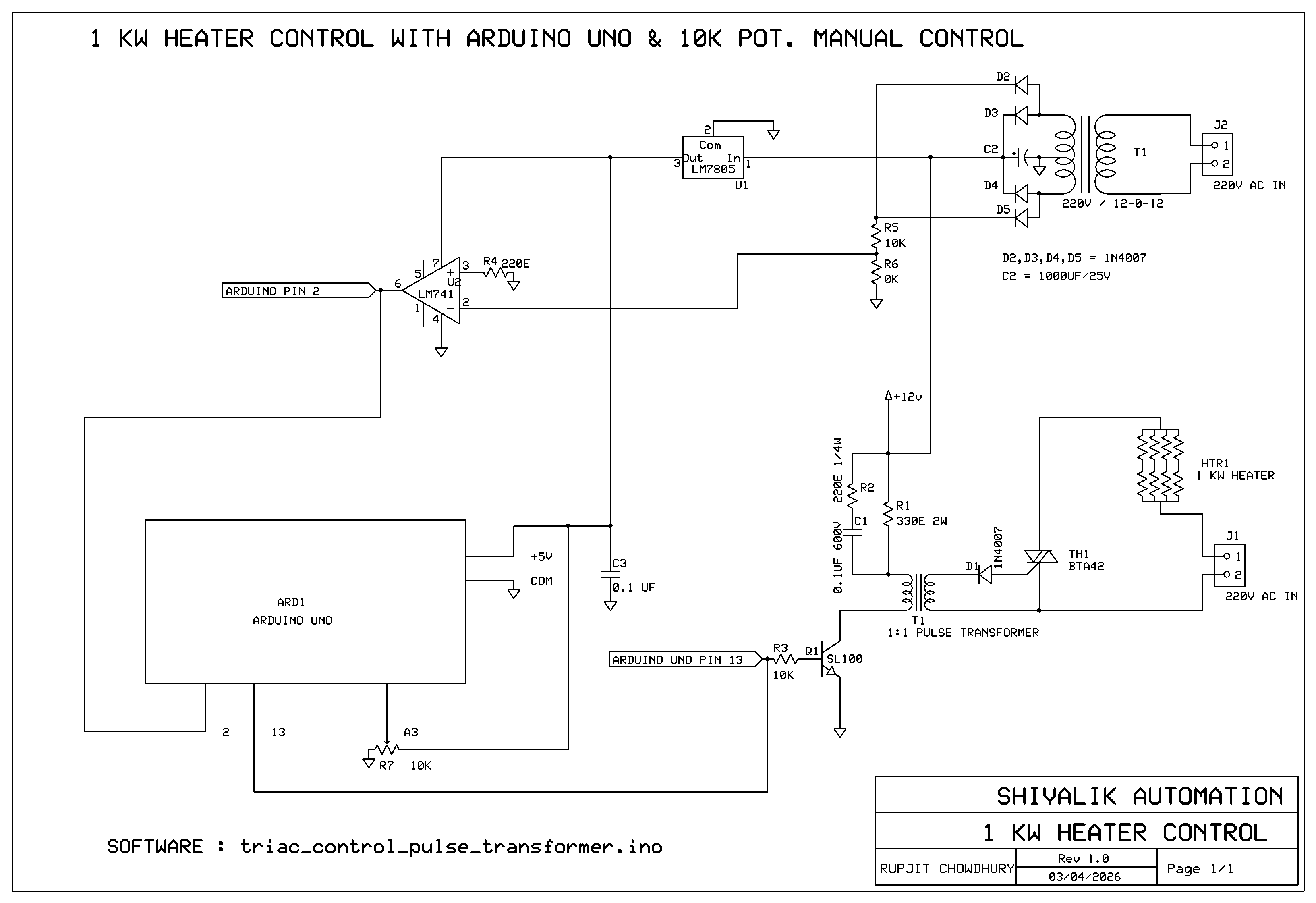
Circuit Diagram
Bill of Materials
ARD1 ARDUINO UNO
C1 0.1UF 600V
C2 1000UF 25V
C3 0.1 UF
D1 1N4007
D2 1N4007
D3 1N4007
D4 1N4007
D5 1N4007
HTR1 1 KW HEATER
J1 220V AC IN
J2 220V AC IN
Q1 SL100
R1 330E 2W
R2 220E 1/4W
R3 10K
R4 220E
R5 10K
R6 10K
R7 10K
T1 1:1 PULSE TRANSFORMER
T1 220V / 12-0-12
TH1 BTA42
U1 LM7805
U2 LM741
Software for Arduino Uno
// TRIAC CONTROL WITH PULSE TRANSFORMER
//1:1 PULSE TRANSFORMER
long interval;
int analogPin = A3;
int val = 0;
const byte ledPin = 13;
const byte interruptPin = 2; // input pin that the interruption will be attached to
volatile byte state = LOW; // variable that will be updated in the ISR
void setup() {
pinMode(ledPin, OUTPUT);
pinMode(interruptPin, INPUT_PULLUP);
attachInterrupt(digitalPinToInterrupt(interruptPin), blink, LOW); //LOW is used as FALLING has noise that causes circuit malfunction
Serial.begin(9600);
}
void loop() {
digitalWrite(ledPin, LOW); // sets the pin off
val = (1023-analogRead(analogPin)); // potentiometer zero is heater output zero
// Scales potValue from (0-1023) to (500ms-5000ms)
interval = map(val, 0, 1023, 0, 9000);
//Serial.println("val");
//Serial.println(val);
//Serial.println("interval");
//Serial.println(interval);
}
void blink() {
delayMicroseconds(interval);
digitalWrite(ledPin, HIGH); // sets the pin on
delayMicroseconds(50); // pauses for 50 microseconds
digitalWrite(ledPin, LOW); // sets the pin off
delayMicroseconds(9000-interval); // prevents further pulses
}
Results
Zero Crossing detector input and output waveforms:
Yellow pen is the zero crossing detector input and green pen is the output. 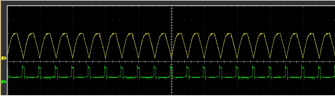
Zero crossing detector and Arduino output waveforms:
Yellow pen is the Zero crossing detector output and green pen is the pulse transformer command. 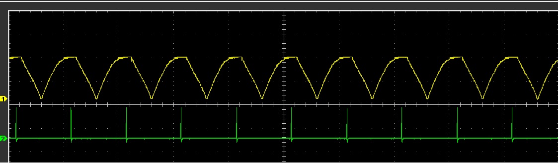
Conclusion
Zero Crossing detector input and output waveforms:
The circuit runs on 220V AC main line. All cares must be taken while making this circuit. Triac used in this circuit is BTA41.
The circuit response is very good and reliable.