SPWM H bridge control with Arduino uno at 50Hz using gate drivers built on MCT2E & TIP122 .
Introduction
In this design I am going to demonstrate H - bridge using mosfets IRF840. The intention of this H - bridge is to work on 50hz frequency supplied
by Arduino uno. The gates of mosfet are fired using optocoupler MCT2E and a transistor TIP122. The circuit has a limitation of 24V DC on H bridge
supply because the components are limited for low voltage applications. We are using digitally generated SPWM or Sine wave Pulse width modulated
waveform to fire the H bridge mosfets.
Description
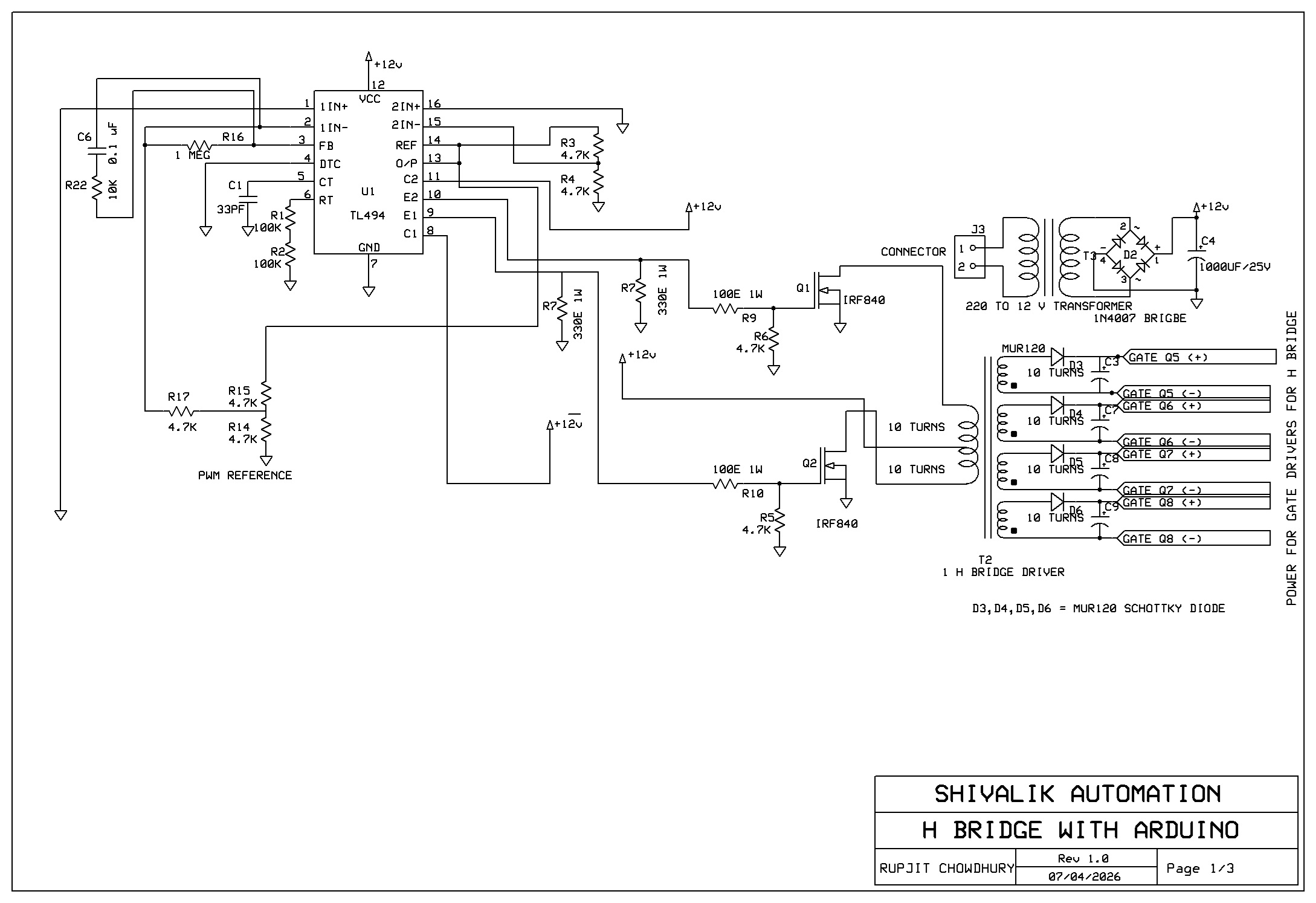
The Gate control circuit power management : The circuit is controlled by U1 i.e. IC TL494. This is the main PWM controller IC.
R1+R2 in parallel to C1 makes a frequency of 53Khz. Pin 8 and Pin 11
are collector pins and they are pulled up to +12V DC. The IC U1 is also powered by +12V DC. Pin 9 an 10 are emitter pins of IC TL494 and they drive
the driver transformer T2. The transformer T2 has 4 secondary windings connected to Schottky diodes D3,D4,D5,D6 and capacitors C3,C7,C8,C9 forming a
half wave bridge rectifier filter based power supply to power the gate control circuit of mosfets Q5,Q6,Q7,Q8.
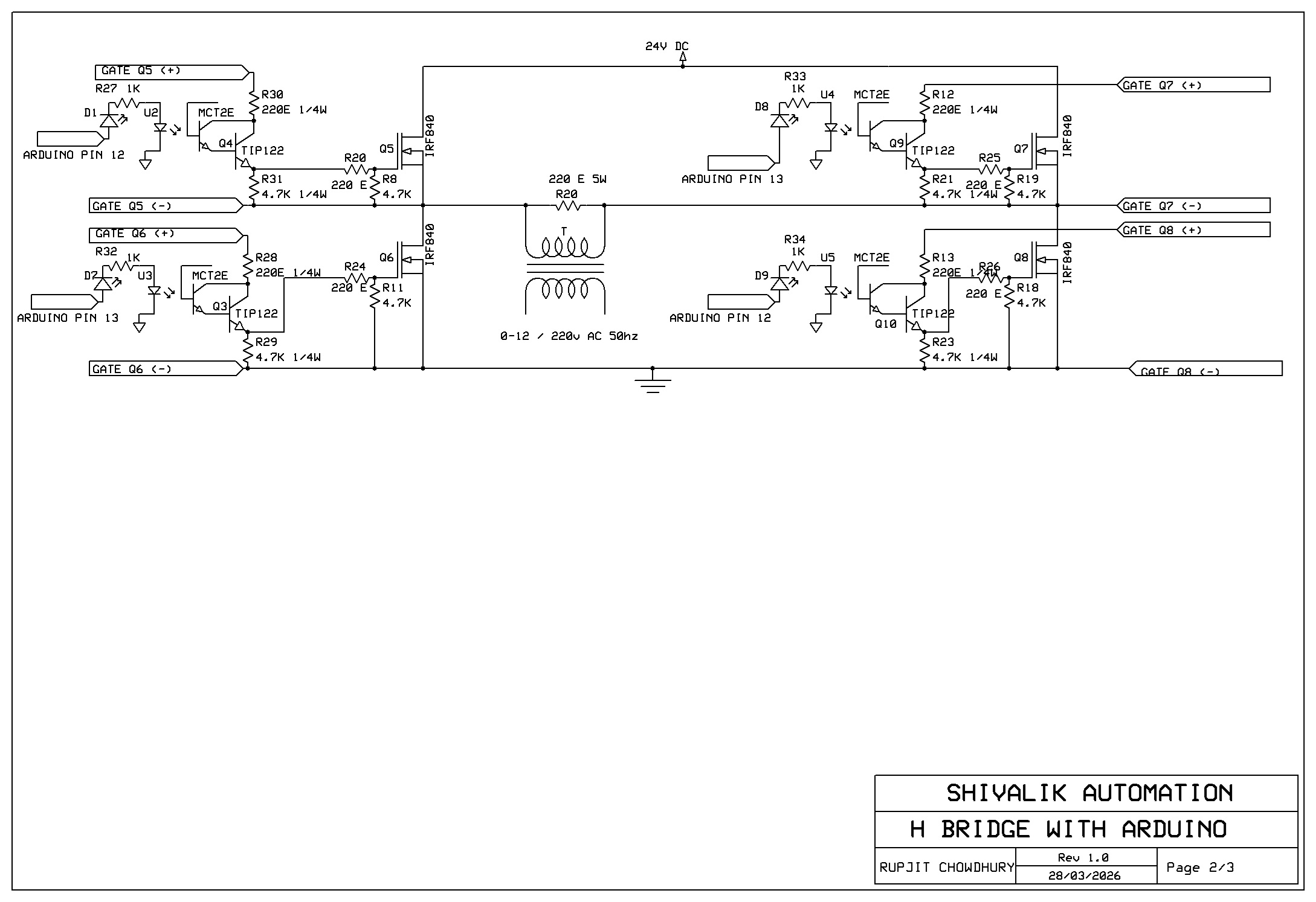
Gate control circuit: The gate control circuits are separate for each mosfet Q5,Q6,Q7,Q8. As discussed in the previous section, these four gate control circuits are powered
individually. Now we discuss a single gate driver. The gate driver uses optocoupler MCT2E and transistor TIP122. MCT2E transistor is connected to transistor
TIP122 in Darlington configuration. The emitter of TIP122 is connected to a 4.7K resistor. Also the collector of the Darlington pair is connected to power
supply through current limiting resistor of 220 Ohm. This block is repeated for all four mosfets. Q5 and Q7 are high side mosfets and the gate control
circuits get a voltage higher than the gate control voltage. The gate control circuits are controlled by Arduino Uno. MCT2E is opto isolator and it isolates
the circuit from the Arduino.
The software used in this circuit generates SPWM wave. SPWM is Sine wave PWM. We are obtaining SPWM waveform digitally Using Arduino Uno. See the Arduino software
attached in software section to view how SPWM waveform is generated.
H-bridge power stage: The H - bridge is made of four mosfets Q5, Q6, Q7, Q8. These mosfets are triggered with correct polarity at their respective gates. The circuit is controlled
by Arduino Uno that is optically isolated. The software in Arduino generates a square wave and is fed to the gate control circuits which finally control the
H bridge. The circuit is a reference circuit working at 24V DC only.
Circuit Diagram
Bill of Materials
Click here for bill of materials
Software - Arduino Uno code for 50 hz SPWM wave
//50 hz oscillator SPWM
int outPin12 = 12; // digital pin 12
int outPin13 = 13; // digital pin 13
//-- i_track always less than m_track --------------------------
//(70*71)+30 = 5000 us
// 5000us ON & 5000 us OFF = 10000 us
int i_track = 70; // track constant in for loop
int m_track = 71; // track parameter in for loop
int padding = 30;// padding if i_track*m_track < 0.01 s
int track ;
void setup() {
pinMode(outPin12, OUTPUT); // sets the digital pin as output
pinMode(outPin13, OUTPUT); // sets the digital pin as output
}
void loop() {
track=1;
for (int i = 0; i <= i_track; i++) {
digitalWrite(outPin12, HIGH); // sets the pin on
digitalWrite(outPin13, LOW); // sets the pin
delayMicroseconds(track); // pauses for 50 microseconds
digitalWrite(outPin12, LOW); // sets the pin off
digitalWrite(outPin13, LOW); // sets the pin
delayMicroseconds(m_track-track); // pauses for 50 microseconds
track++;
}
//delayMicroseconds(30); // total = 70*71+30 = 5000 us (30 us is at end of this cycle)
track=1;
for (int i = 0; i <= i_track; i++) {
digitalWrite(outPin12, HIGH); // sets the pin on
digitalWrite(outPin13, LOW); // sets the pin
delayMicroseconds(m_track-track); // pauses for 50 microseconds
digitalWrite(outPin12, LOW); // sets the pin off
digitalWrite(outPin13, LOW); // sets the pin
delayMicroseconds(track); // pauses for 50 microseconds
track++;
}
delayMicroseconds(padding); // total = 70*71+30 = 5000 us
// 30 us + 30 us = 60 us gap kept here
//when 13 IS ON 12 IS OFF
track=1;
for (int i = 0; i <= i_track; i++) {
digitalWrite(outPin13, HIGH); // sets the pin on
digitalWrite(outPin12, LOW); // sets the pin
delayMicroseconds(track); // pauses for 50 microseconds
digitalWrite(outPin13, LOW); // sets the pin on
digitalWrite(outPin12, LOW); // sets the pin off
delayMicroseconds(m_track-track); // pauses for 50 microseconds
track++;
}
//delayMicroseconds(30); // total = 70*71+30 = 5000 us
track=1;
for (int i = 0; i <= i_track; i++) {
digitalWrite(outPin13, HIGH); // sets the pin on
digitalWrite(outPin12, LOW); // sets the pin on
delayMicroseconds(m_track-track); // pauses for 50 microseconds
digitalWrite(outPin13, LOW); // sets the pin on
digitalWrite(outPin12, LOW); // sets the pin off
delayMicroseconds(track); // pauses for 50 microseconds
track++;
}
delayMicroseconds(padding); // total = 70*71+30 = 5000 us
//5000+5000 us = 10000 us = 10 ms = 50hz half cycle
}
Results
Waveforms:
SPWM wave output waveforms at 50 Hz - 1. 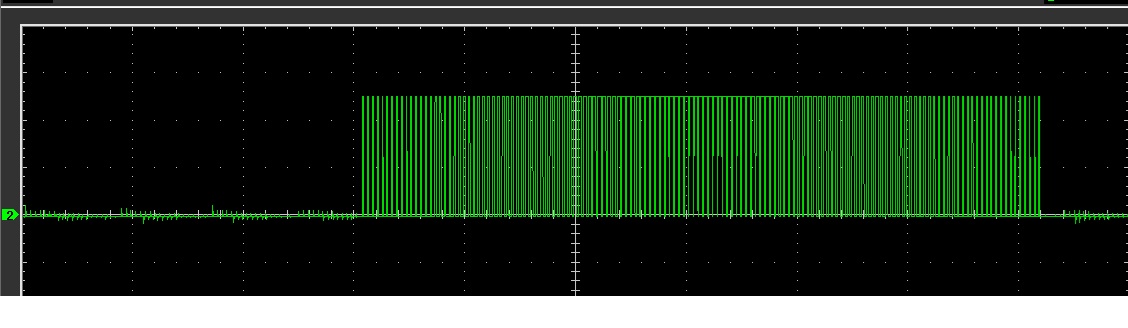
Waveforms:
SPWM wave output waveforms at 50 Hz - 2. 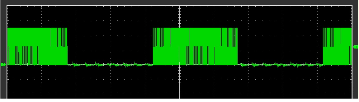
Waveforms:
SPWM wave output waveforms at 50 Hz - 3. 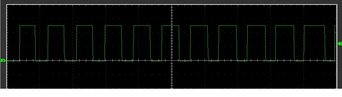
Conclusion
The circuit is built as a reference design. Please watch the performance on the youtube link provided.